2 . The status line prompts, "Add: Curved Grid". Various locators become active along with Locate - Pan - Return mouse bindings. Left-click (Locate) the first point. This point is the end of the grid line.
Alternative: Press Esc or right-click (Return) to end the command.
3 . The status line prompts, "Locate second point". Left-click (Locate) a second point. This point is the opposite end of the grid line.
Alternative: Press Esc or right-click (Return) to end the command.
4 . The status line prompts, "Locate third point". Left-click (Locate) a third point. This point sets the direction, radius, and arc length of the curved grid line.
Alternative: Press Esc or right-click (Return) to end the command.
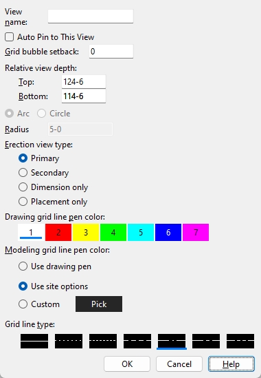
5 . The Add Curved Erection View window appears. When you are done adjusting the settings, click OK to add the curved grid.
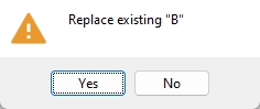
Alternative 1: If the name in the View name field matches an existing erection view or curved grid line, you will be prompted to verify the replacement of the existing view/grid. Click Yes to replace the existing view/grid. Click No to cancel the replacement and repeat step 2.
Alternative 2: Click Cancel to end the command.
6 . The status line prompts, "Add: Curved Grid", allowing you to continue adding curved grid lines beginning at step 2.
Alternative: Press Esc or right-click (Return) to end the command.
Unlike straight grid lines, which can be added using Add Grid Line, curved grid lines cannot be opened as views.
Curved grid lines also cannot be auto detailed as erection views. They can, however, be drawn on other erection views when you Detail Erection Views and choose to Annotate erection views.
Curved grid lines can also be snapped to for point location using Locate options such as INCM and INCL.
 Add Curved Grid, 3 Points
Learn more about alternative methods for launching commands.